Can I use a relay or contactor with Mercator Ikuü smart switches to drive DC or high power loads?
Applicable products:
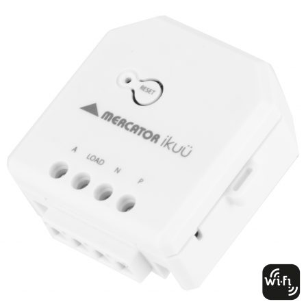
- SSWM/SSWM-WIFI
- SSWM10-ZB/SSW10-WIFI
- SSW01G/SSW01GMBK/SSW01G-WIFI
- SSW02G/SSW02GMBK/SSW02G-WIFI
- SSW03G/SSW03GMBK/SSW03G-WIFI
- SSW04G/SSW04GMBK/SSW04G-WIFI
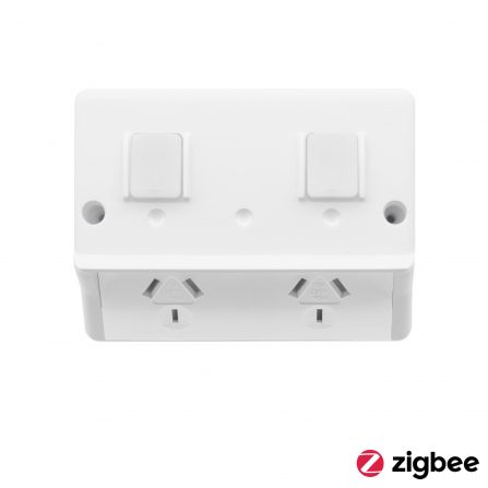
- SSW01GN-ZB
- SSW02GN-ZB
- SSW03GN-ZB
- SSW04GN-ZB
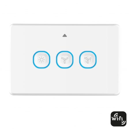
- SSW01GX-ZB/SSW01GX-WIFI
- SSW02GX-ZB/SSW02GX-WIFI
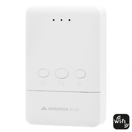
- SISW11-ZB/SISW11-WIFI
The above Mercator Ikuü smart switches can drive a relay or contactor to power the following loads:
- Direct current loads with an appropriate DC source
- Alternating current loads that are rated above the maximum allowable listed on the Mercator Ikuü smart switch
Follow the guidelines below, noting that the below is general advice only – the certifying electrician should consider the specifics of the project site in conjunction with this information.
Ensure an appropriate relay or contactor is chosen for the load and the circuit is rated for the required use case. In addition:
- Use a mechanically switching relay or contactor
- The coil component must be rated for 240VAC
- The coil power is recommended to be below 5W
For the following Mercator Ikuü smart switches, a load correction capacitor is required to be attached parallel to the coil circuit (shown in circuit diagram below) to meet the minimum load requirement of the product. Use at least a Type X2 0.68uF 250VAC capacitor
- SSWM/SSWM-WIFI
- SSW01G/SSW01GMBK
- SSW02G/SSW02GMBK
- SSW03G/SSW03GMBK
- SSW04G/SSW04GMBK
Connection Diagram:
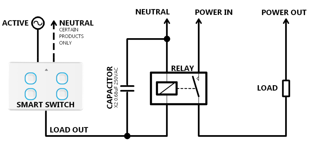
Note: Certain Mercator Ikuü smart switches do not possess a neutral terminal
- Connect the LOAD terminal from the Mercator Ikuü smart switch to the input of the relay coil. Ensure an appropriate relay or contactor is chosen for the load and the circuit is rated for the required use case
- Connect the output of the relay coil to neutral. Ensure a load correction capacitor is connected in parallel to the relay coil circuit where required
- Connect the source power (power in) for the load to the switching input of the relay or contactor
- Connect the switching output of the relay or contactor to the load
- Connect the load to the sink power (power out) for the load